|
Wireless I/O Radio
Application:
Bidirectional 900 MHz or 2.4 GHz Spread Spectrum
Radios Link 4-20mA Sensor Current Loops,
Discretes, and Relay I/O
Model: DIN-R
Typical Site
Application Diagram:
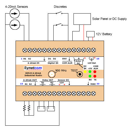
Every
input signal (4-20mA, digital) on one wireless
i/o radio appears as an output on the other
radio. The radios are set up as pairs that
emulate a cabled connection. Nothing to
configure or calibrate. I/O connects
directly to labeled terminals. Internal
solar panel, battery charger, and sensor power
supply make remote site applications easy.
1. 4-20mA
sensors are powered by the DIN-R's internal
Sensor DC supply. Sensor current loops
input to radio 1 are output as loop-powered
4-20mA current loops on radio 2.
2.
Grounding Digital INs on radio 1 causes
corresponding Relay OUTs on radio 2 to assert.
3.
Likewise, inputs on radio 2 appear as outputs on
radio 1.
For
applications with more than two sites, or with
expandable Wireless I/O requirements, use
Synetcom's
Serial
SCADA Radio Modem
with Radio
Telemetry I/O Expanders.
|